
Producing Solar-Recycled Plastic Irrigation Connectors
Author: Maria Monica Cabarcas Granados
Role: Product Designer
Context: Sun Factory Project
Fablab Benfica
IPL Lisbon
Oltre formazione
Lisbon Residency 2026: https://hub.antenna.ch/node/206
Introduction
In the contemporary environment, pollution is a problem that encompasses a large part of current global issues. With the industrial production of plastic in the 1950s, it has become one of the most manufactured materials worldwide. A study conducted by the European Parliament reveals that current plastic production exceeds 359 million tonnes, and that 40% of it is destined for immediate disposal as packaging (Pinto da Costa et al., 2020). These figures indicate that plastic is one of the biggest pollutants, an undeniable problematic considering that its most widely used variation, polyethylene terephthalate (PET), takes 400 to 500 years to decompose (National Geographic, 2024; Nalgene, 2025). Therefore, as a way to counteract the environmental impacts resulting from its accumulation and reduce the amount of plastic waste generated, the idea of recycling it has emerged.
The Sun Factory project is an initiative focused on promoting decentralized plastic recycling using solar thermal energy, with the goal of transforming this material into new products without relying on electricity. The project also aims to facilitate access to low-cost recycling technologies by providing plans, tools, and training so that communities, schools, organizations, and manufacturers can build and operate their own recycling centers, thus fostering a circular economy and reducing the environmental impact of plastic waste. In doing so, the project directly contributes to Sustainable Development Goal 7 “Affordable and Clean Energy”, through its reliance on solar power as the primary energy source, and Sustainable Development Goal 12 “Responsible Consumption and Production” (United Nations, n.d.), by promoting the reuse of plastic waste and encouraging more sustainable production practices at a community level.
In line with the project's main objective, this article will describe an essential part of the recycling process: the design and creation of a plastic injection mold. Specifically, it will focus on the development of a hose connector as a practical application of recycled plastic, covering the stages of product selection, 3D modeling, mold design, material selection, and manufacturing through 3D printing. Additionally, the article will document the collaboration with the contributors Emanuele Ceridono and Federico Guizzo during the solar injection stage, analyzing the technical considerations involved in obtaining a functional mold and evaluating the challenges of solar-powered recycling as an alternative approach for transforming plastic waste into new products.
Molds for plastic injection
A plastic injection mold is the component responsible for shaping the object manufactured through the injection molding process. It is designed with one or more cavities that precisely reproduce the geometry of the final part, allowing the molten plastic material to be distributed in a controlled manner. Its main function is to contain and guide the flow of plastic under pressure so that, after cooling and solidifying inside the cavity, a part with the required dimensions, details, and characteristics is obtained.
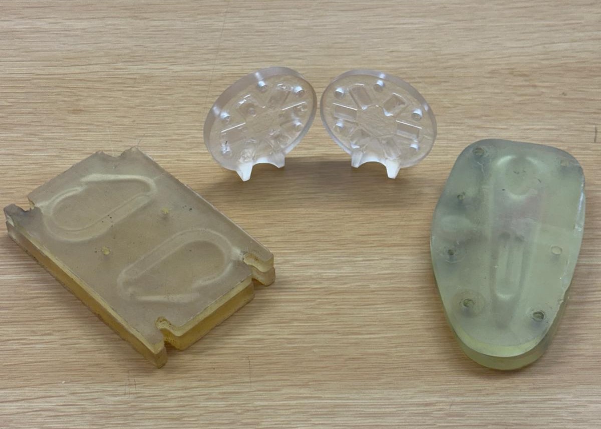
During the injection molding process, the plastic is first heated until it reaches a molten state and is then injected under pressure into the mold cavity, where it conforms to the desired geometry. As the material cools and solidifies, the mold is opened and the finished part is ejected. While industrial injection molds are typically manufactured from steel or aluminum because of their strength, durability, and ability to withstand repeated production cycles, this project employs molds made of transparent resin. The use of this material enables direct observation of how the molten plastic fills the cavity during injection, facilitating the analysis of material flow behavior; below are some of the injection molds used at Sun Factory project.
Product Design
Product design, in its essence, begins with the analysis of needs that arise in everyday life. Every useful object is born from a real problem that requires a practical, functional, and accessible solution. Based on this premise, the selection of the object to be designed in this project was founded on the identification of a common household need: the efficient and safe connection of hoses for watering, cleaning, and home maintenance.
A hose connector was chosen because it is a frequently underestimated item within the universe of household tools, despite being essential for ensuring a constant water flow, preventing leaks, and facilitating quick coupling between hose sections or fittings. Hose connectors are widely used components in irrigation systems, gardening, plumbing, and industrial applications, and technical guides describe them as common or standard connectors in these contexts (Collister & Glover, 2024). There are many types of connectors that vary according to dimensions, size, geometry, material, etc.
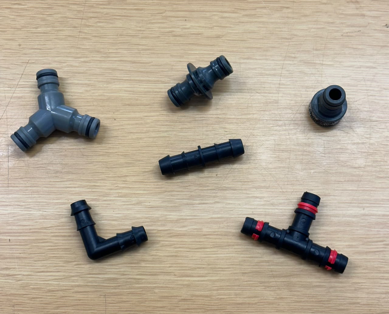
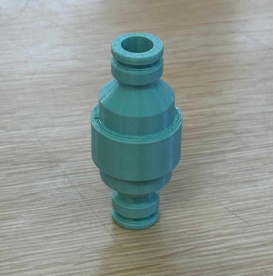
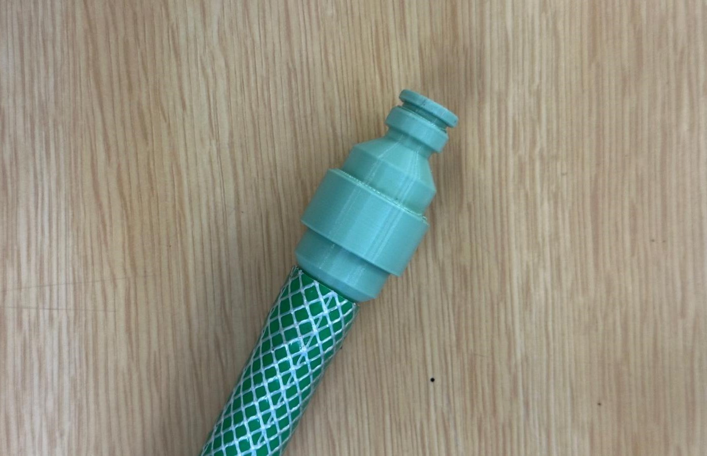
To develop the 3D model of the hose connector, a research and reference process was necessary to understand the proportions, geometries, and technical characteristics that this type of fitting must meet to guarantee its proper functioning. Various models available on the market were analyzed, identifying aspects such as the coupling diameter, thread system, wall thickness, and overall shape of the part. Based on this analysis, it was decided to design a 15 mm hose connector, a size that corresponds to one of the most commonly used diameters in household hoses, ensuring greater compatibility with readily available fittings. This modeling process was carried out using Onshape, a cloud-based CAD software.
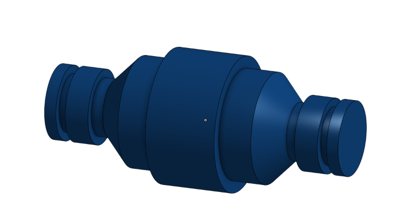
The resulting model of the hose connector was developed from a profile sketch, which served as the basis for generating the final geometry of the object using 3D modeling tools. This design approach, based on a scalable profile, made the final product to be not limited to the initially planned 15 mm connector, but could be easily adjusted and adapted to different hose diameters. In this way, the developed design offers a flexible and replicable solution, capable of meeting diverse coupling needs without requiring a complete redesign of the part. This represents a significant advantage in terms of efficiency and versatility.
3D printing with filament
To verify the functionality of the designed part, a test version of the hose connector was printed using generic PETG filament on a Bambu Lab A1 Mini printer. This validation stage was crucial before proceeding with mold development, as it confirmed that the geometry and dimensions defined during 3D modeling were effectively translated into a functional object, capable of fitting correctly and fulfilling its intended purpose. Once the printed result was confirmed to function properly, it was possible to proceed with the design and development of the corresponding mold.
Mold Creation
Once the model of the hose connector was created and validated, it was possible to proceed with the development of the corresponding mold, a process also carried out using Onshape software. Designing a mold involves an additional level of complexity compared to designing the part itself, since it is not enough to define the geometry of the final object; it is also necessary to consider aspects such as the parting line, the draft angle, material shrinkage during cooling, injection channels, and the ease of removing the part once solidified. All these factors had to be taken into account when transforming the connector model into a functional tool capable of reproducing that geometry through the injection molding process of recycled plastic melted with solar energy.
Since this was a new process with multiple technical variables involved, the mold development was not linear, but rather carried out through a trial-and-error method, resulting in two different versions throughout the project. The first version revealed limitations in the design and the behavior of the mold during printing and injection molding. This information proved crucial for developing a second, improved version, which aimed to correct the identified problems and optimize the final result. The design, printing, testing, and results obtained for each of these two versions are described in detail below, with the purpose of demonstrating the project's evolution, the decisions made at each stage, and the improvements resulting from this iterative process.
Mold: First version
Given that this was the first version of the mold, it was decided to design it without the hole, since including it at this stage would considerably complicate the demolding process. Incorporating an internal hole would require additional mechanisms or a more complex mold geometry for its proper extraction, increasing the risk of defects or damage to the piece during removal. For this reason, it was determined that the hole would instead be made manually once the piece was removed from the mold.
Design
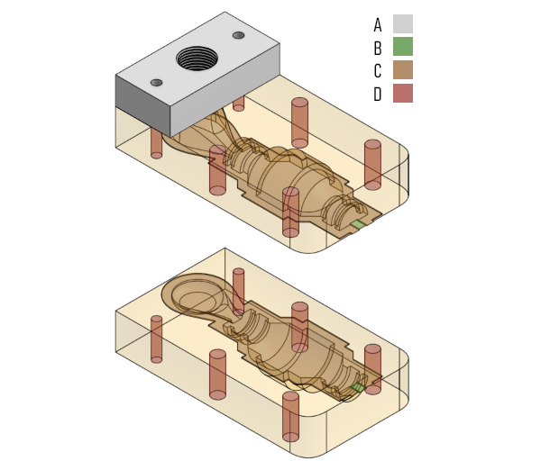
Based on the product selected, it is done a sketch that demonstrates the logic behind the pieces. Since every mold is oriented to an specific object, it should follow a different solution that adheres to the needs, by doing so, it may vary in the quantity of pieces, size, number of screws, orientation and so on. The design features that defines the mold are:
A. Opening for injection: Corresponds to the point through which the melted plastic is introduced into the mold cavity. Its size, position, and shape is pre-defined by the injection bracket to ensure a controlled flow of material, avoiding premature solidification or uneven filling of the mold. This opening was designed considering the characteristics of the solar injection process, ensuring that the melted plastic could reach the entire cavity before cooling down.
B. Air outlet: Designed as a controlled outlet that permits excess material or trapped air to escape during the injection process. This feature helps prevent pressure buildup inside the mold, reduces the likelihood of defects such as bubbles or incomplete filling, and contributes to a cleaner, more precise final result.
C. Lock: Refers to the mechanism used to keep the different pieces of the mold securely aligned and closed throughout the injection process. This element works together with the screws to ensure that the mold does not shift or separate under pressure, maintaining the precision of the cavity and guaranteeing that the resulting piece faithfully reflects the intended design of the hose connector.
D. Screws: The number of screws and their distribution across the mold were determined by the need to keep the different pieces of the mold firmly joined together during the injection process. An adequate distribution of screws prevents the mold from opening or shifting due to the pressure generated by the melted plastic, ensuring a tight seal along the parting line and contributing to the accuracy and consistency of the final piece.
E. Number of pieces: It depends directly on and is defined by the demolding process designed for the piece. Dividing the mold into separate pieces makes it possible to create the internal cavity corresponding to the shape of the hose connector, while also facilitating the assembly and disassembly process required for each injection cycle.
F. Orientation of the object: Refers to the position in which the hose connector is placed during the design of the cavity, and it plays a key role in the quality of the final piece. An adequate orientation facilitates the flow of melted plastic throughout the mold, reduces the risk of trapped air or incomplete filling, and simplifies the extraction of the piece once it has solidified. For this reason, defining the correct orientation was one of the most important decisions made during the design.
G. Size and dimensions: The overall external dimensions of the mold had to be considered in relation to the printing process, guaranteeing that the mold could be manufactured within the limitations of the available 3D printer while maintaining sufficient structural strength to withstand the injection process.
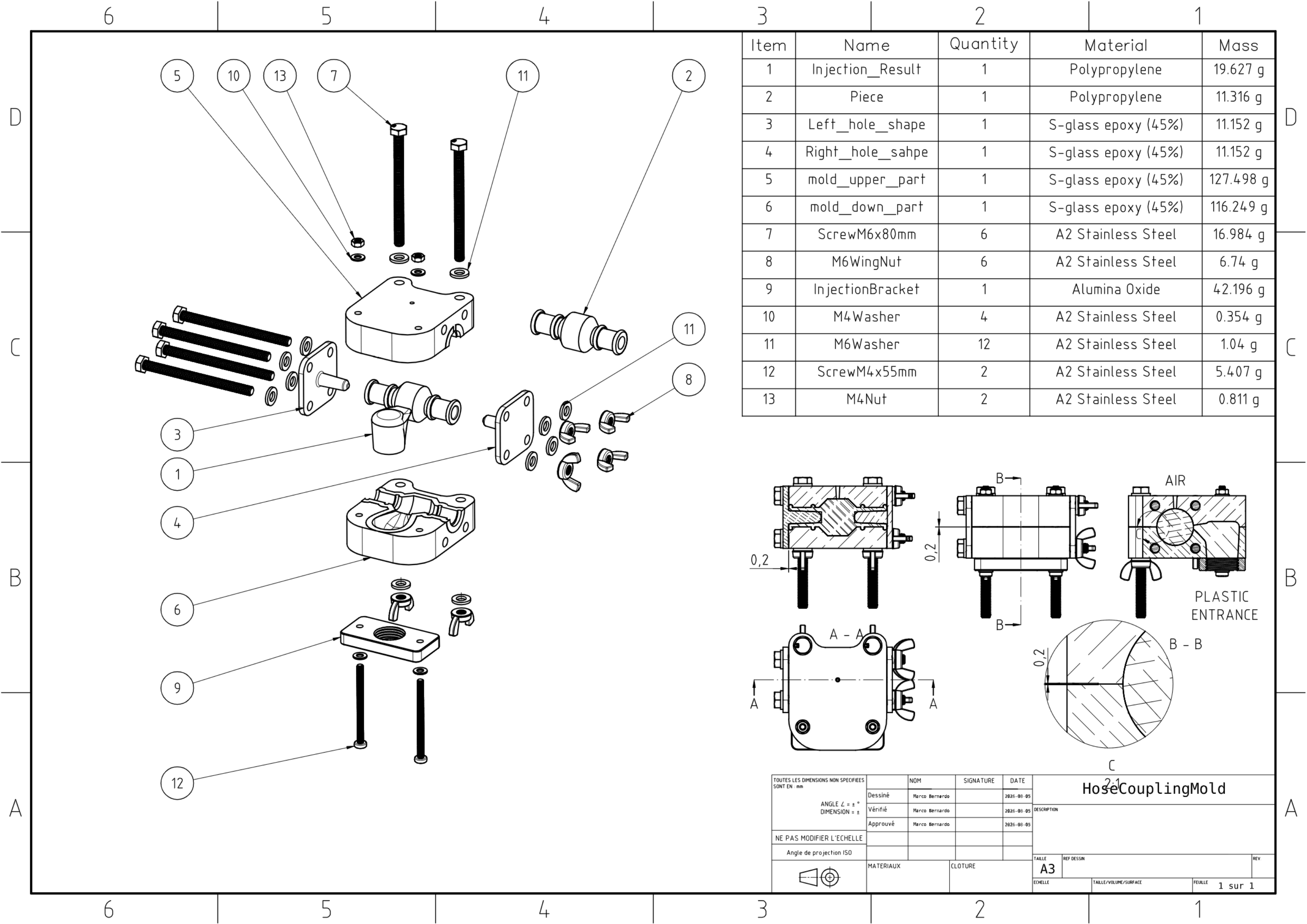
The outcome is a two-piece mold that uses four M6 screws and two M4 screws, along with one injection bracket. M6 screws were placed to prevent the mold halves from separating under the force of the melted plastic, while the two M4 screws were specifically used to secure the injection bracket in place, ensuring it remained properly aligned with the cavity throughout the injection process.
Resin printing
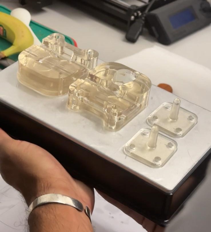
Once the mold design was finalized, it was manufactured using 3D resin printing with the Uniformation GKtwo printer. This printing process was chosen over the filament previously used for testing the part because resin possesses essential characteristics for a mold that must withstand the temperatures of the injection molding process and accurately reproduce the geometry. Furthermore, a transparent resin was selected, as this characteristic facilitates visual verification of the molten plastic flow within the cavity during the injection process, making it possible to identify potential air bubbles, incomplete filling, or other irregularities without needing to open or damage the mold.
The two mold pieces were printed together, and given the geometry of the piece, it was determined that no support structures were required for a successful print. The pieces were oriented at a 90-degree angle along the Z-axis, positioning the flat, smooth surface of the mold facing downward toward the build plate, while the cavity faced upward toward the resin vat. This orientation enabled the resin to flow freely into the cavity during each layer's exposure, ensuring an even cure and a smooth surface finish on the flat side of the piece, without the need for supports that could otherwise leave marks or imperfections on critical surfaces of the mold.
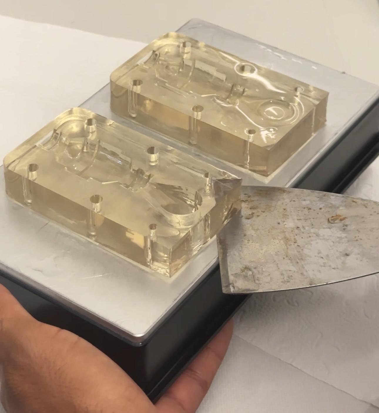
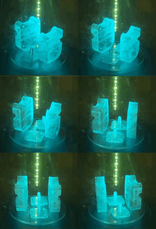
After printing, the pieces were removed from the build plate and were washed using only water, since the resin used was water-washable, eliminating the need for isopropyl alcohol or other chemical solvents at this stage. Afterward, the pieces underwent curing using the Anycubic machine, where the mold pieces were exposed to concentrated ultraviolet light from multiple angles to ensure uniform exposure across all surfaces, including recessed areas such as the cavity. During this exposure, the UV light triggers a photopolymerization reaction within the resin, causing the remaining liquid monomers to cross-link and solidify into a rigid, stable structure. This step is critical, as the pieces come out of the printer only partially cured, lacking the mechanical strength required to withstand the pressures involved in the injection molding process. The rotating platform within the curing chamber further contributed to an even distribution of UV exposure, minimizing the risk of under-cured spots that could compromise the durability or dimensional accuracy of the mold.
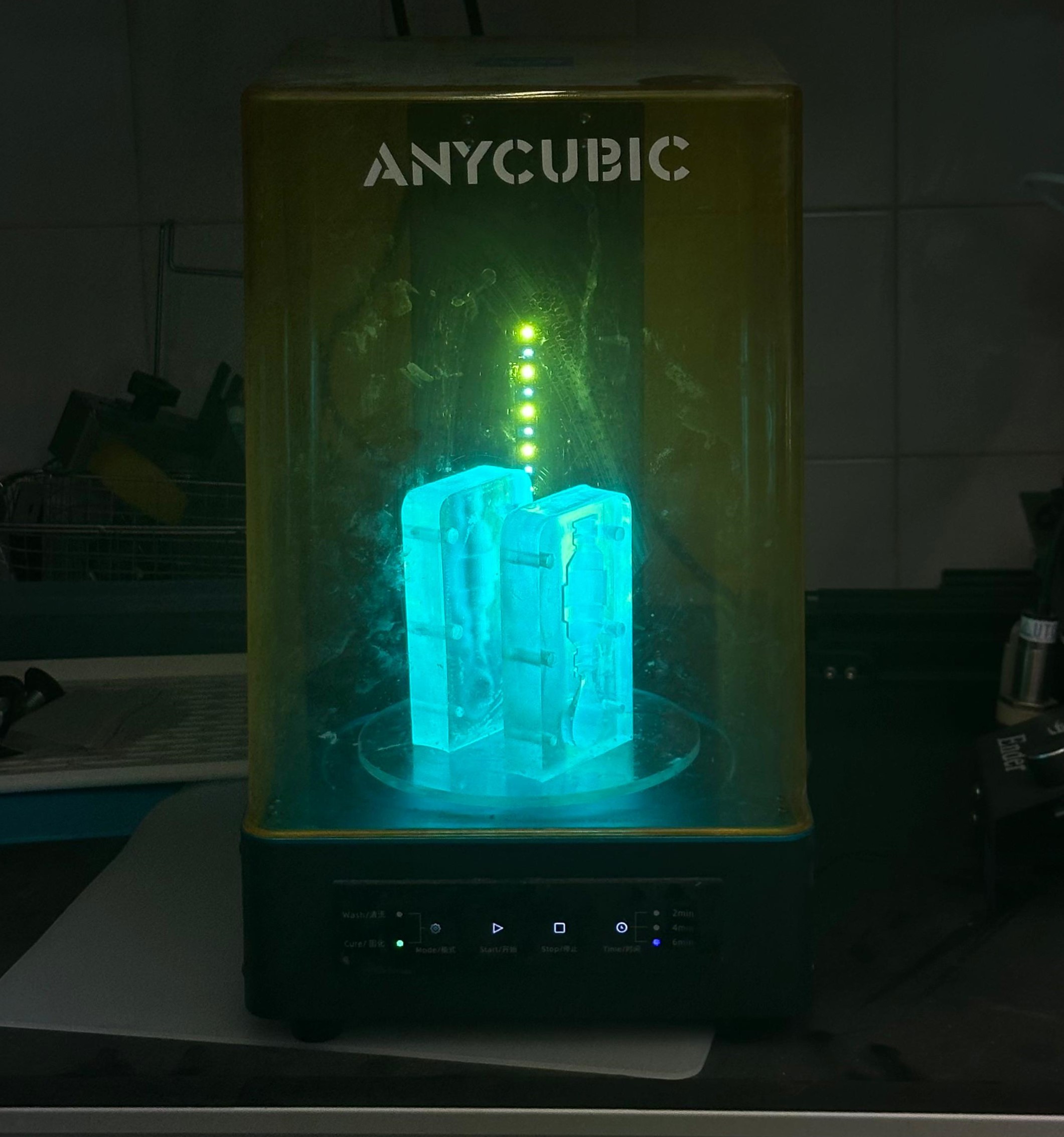
The curing stage was followed by a light sanding process applied to the exterior faces of the cavity of each mold piece. This step addressed minor surface irregularities left from printing, ensuring a smoother finish along the areas that would come into direct contact between the two mold halves once assembled. By refining these exterior surfaces, a more even fit between the pieces was achieved, reducing the likelihood of gaps along the parting line that could otherwise lead to plastic leakage during the injection process.
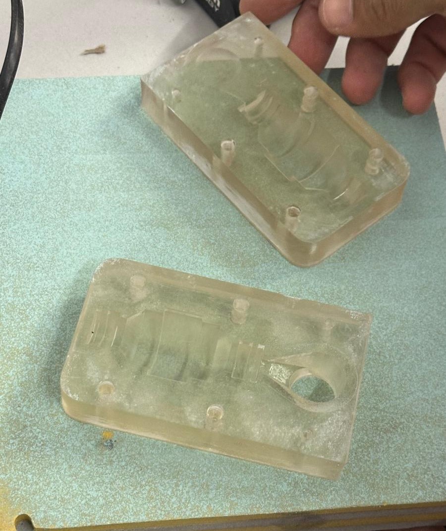
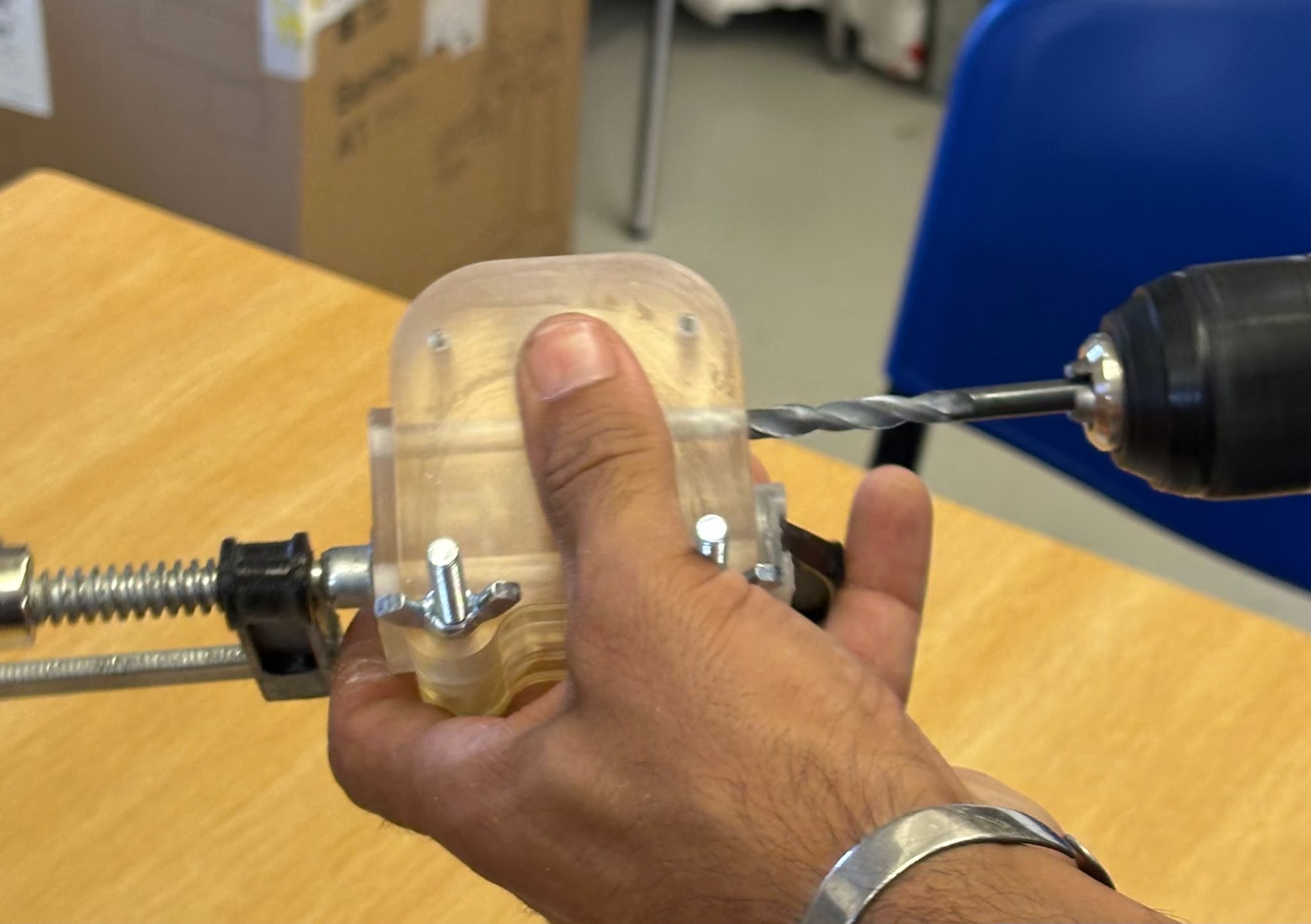
Additionally, a drilling was carried out on the screw holes of the mold. This step was necessary because resin printing does not always guarantee perfectly clean and consistent hole diameters, as minor deviations can occur due to shrinkage during curing or residual cured resin along the inner walls of the holes. Drilling ensured that each hole matched the diameter required for the M6 and M4 screws to pass through smoothly.
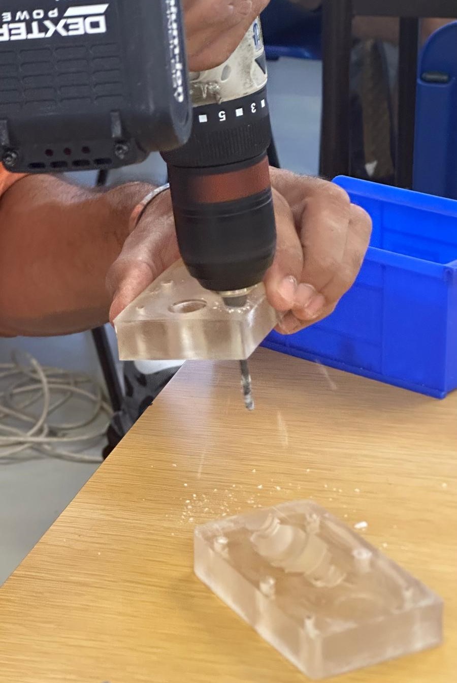
As a result, the mold was left fully finished and ready for use. The two pieces fit together along the parting line, the screw holes were properly calibrated for the M6 and M4 screws. With all post-processing steps completed, the mold met the conditions required to move forward with plastic injection testing.
Solar Injection
Prior to the injection process, the mold required preparation to ensure it was properly set up and ready to withstand the pressure of the melted plastic. This involved aligning the two mold pieces along the parting line and securing them together by inserting and tightening the M6 screws, which provided the main clamping force, along with the M4 screws holding the injection bracket firmly in place. Special attention was given to tightening the screws evenly across all points, as uneven pressure could create small gaps along the parting line and lead to plastic leakage during injection.
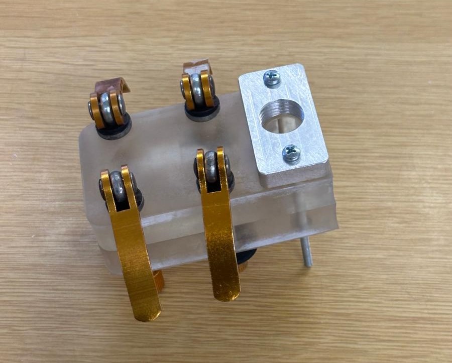
The next step, the plastic injection, consists of placing recycled plastic inside a cartridge, which is then exposed to concentrated solar energy until the material reaches the required processing temperature, depending on the type of plastic used (190–200°C for polypropylene (PP) and 205–215°C for high-density polyethylene (HDPE)). Once the plastic has completely melted, it is injected into the previously designed mold, where it takes on the shape of the cavity and, upon cooling, solidifies into the final piece. During operation, the cartridge refresh time should not exceed 50 seconds when the temperature decreases from 200°C to 180°C. This method takes advantage of solar energy as a clean and low-cost heat source, eliminating the need for electrical or fossil-fuel-based heating systems.
After that, the testing of the mold took place as part of a workshop, aimed at introducing younger audiences to concepts of sustainability, recycling, and renewable energy, spreading awareness about the initiative and demonstrating different applications of solar energy. During this activity, HDPE was the plastic selected for injection, and participants were able to witness firsthand how recycled material could be transformed into a functional piece through a process powered entirely by the sun. Moreover, the workshop provided an educational opportunity to demonstrate different applications of solar energy in an interactive manner.
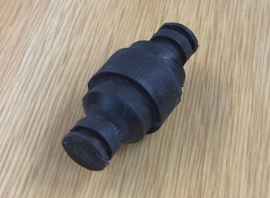
The outcome of this first version is a hose connector produced from recycled HDPE through the solar injection process, exhibiting the double-barbed geometry designed for hose attachment. The piece has visible ridges along its surface corresponding to the mold's parting line, along with a rougher, matte texture. While structurally solid, the piece reflects the experimental nature of this first testing round and, as anticipated during the mold design stage, the piece still lacks the through hole, which was intentionally left out of this first version and will need to be drilled manually to complete the connector's functionality. Nevertheless, the object offers a clear reference point for identifying adjustments to be made in future iterations of the mold and injection.
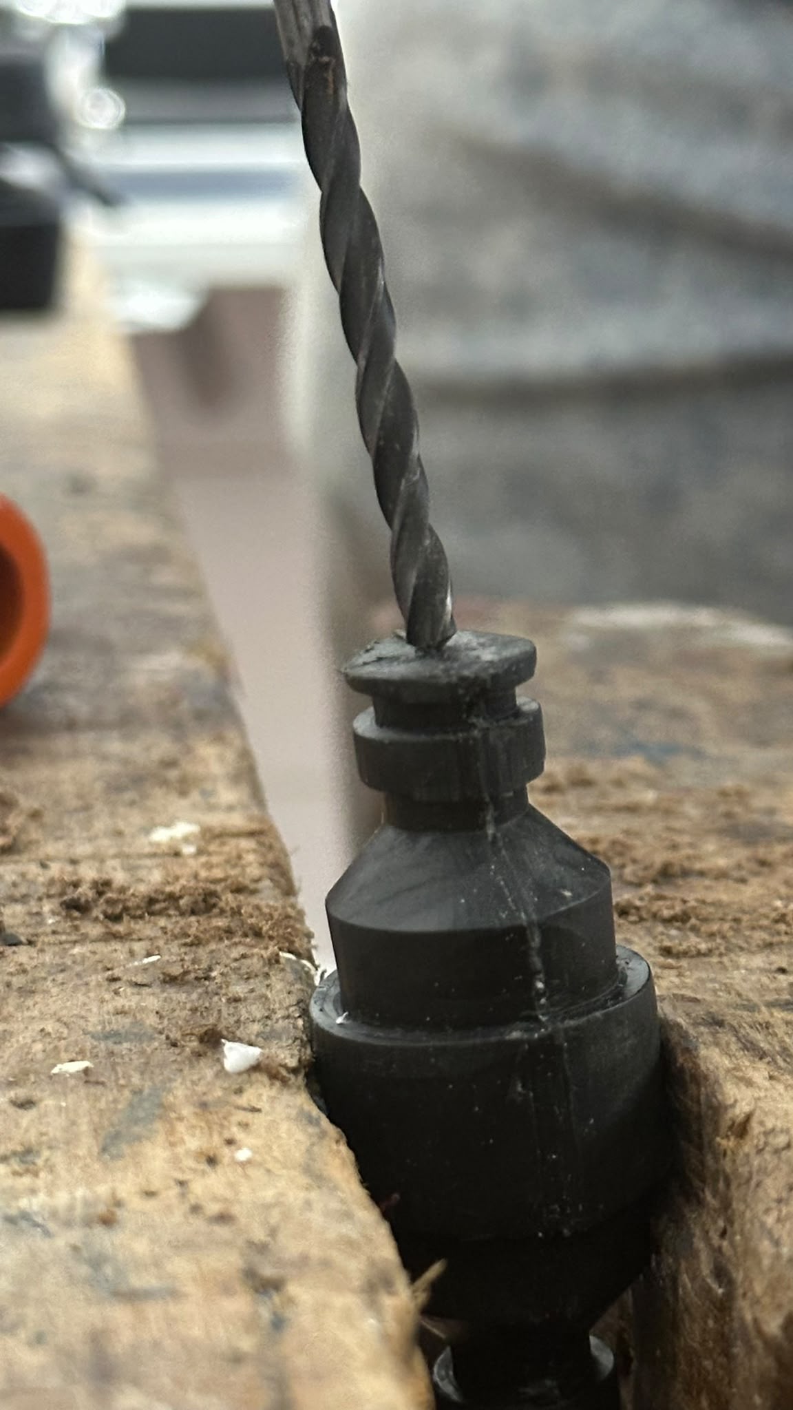
At the same time, it presented several opportunities for improvement, particularly regarding the manual creation of the through hole. Drilling had to be carried out in two directions to fully open the hole along the connector's length. This manual approach also proved challenging in terms of achieving proper centering, as accurately aligning the drill with the central axis of the piece by hand introduced a risk of an off-center or uneven hole, potentially affecting the connector's overall functionality.
Another opportunity for improvement is the resin printing step. While looking at the final piece, a printing error in the mold became evident, as the result is noticeably flattened rather than perfectly round. This deviation from the intended cylindrical geometry likely originated during the resin printing or curing stages, and represents a challenge that will be specifically addressed in the next version of the mold, with adjustments aimed at preserving a more accurate circular cross-section throughout the piece.
While the resulting object revealed specific issues to be addressed, such as the missing through hole and the flattened cross-section caused by a printing error, these findings provide valuable insight for refining the next version of the mold. These are clear and actionable steps toward improving the precision of the mold design and the injection process going forward.
Mold: Second version
Object design
Building on the results and challenges identified during the first testing round, a second version of the hose connector model was developed to improve the manufacturing stage. This new iteration focused on simplifying the object, prioritizing functionality above all else as the main criterion guiding every design decision.
As part of this simplification, non-essential geometric details were removed, streamlining the piece to concentrate on the core elements required for proper hose attachment and plastic flow during injection. The 15 mm diameter established in the first version was preserved, as this dimension had already proven adequate in terms of compatibility with commonly available hoses, leading the redesign effort to focus specifically on improving the demolding of the object.
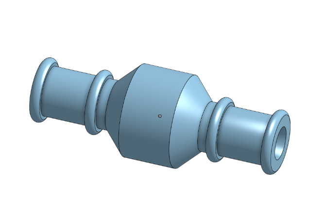
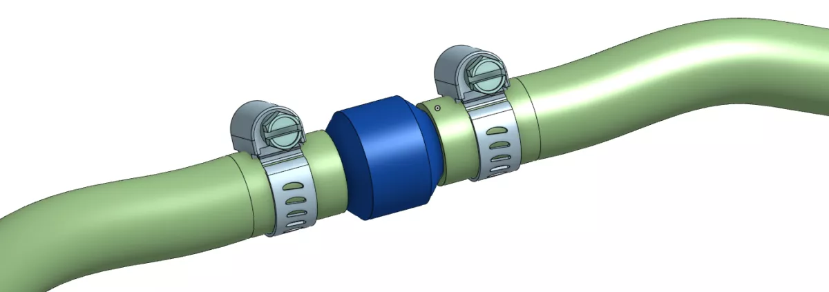
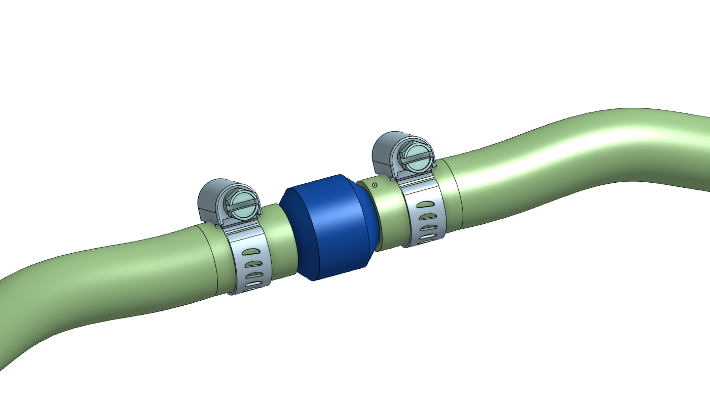
The connector is intended to provide a secure and leak-resistant connection between two flexible hoses during operation. It is designed to maintain continuous fluid flow and ensure proper alignment of the hoses. When assembled, each hose is inserted onto the connector ends and secured with clamps to prevent accidental disconnection caused by pressure, vibration, or movement. The design also facilitates straightforward installation and removal for maintenance or replacement when necessary.
It is necessary to point out that even thought this second mold was intended to incorporate all the design, directly molding the complete hole into the piece remains unfeasible. As the internal geometry required for a straight, fully open channel would prevent proper demolding, the mold would be unable to release the piece without damaging either the connector or the cavity itself. Therefore, the goal is to incorporate guide holes for the drill, reducing reliance on fully manual, unguided drilling to create the connector through hole. This is achieved by including shallow guide indentations at the correct entry points, so the mold provides a fixed reference for the drill, improving alignment and centering while still avoiding the demolding.
Printing with filament
Before proceeding with the mold design for this second version, a test print of the part was made to verify its functionality. For this print, it was necessary to orient the part vertically, as a horizontal orientation would compromise its structural strength and facilitate breakage during the printing or handling process.
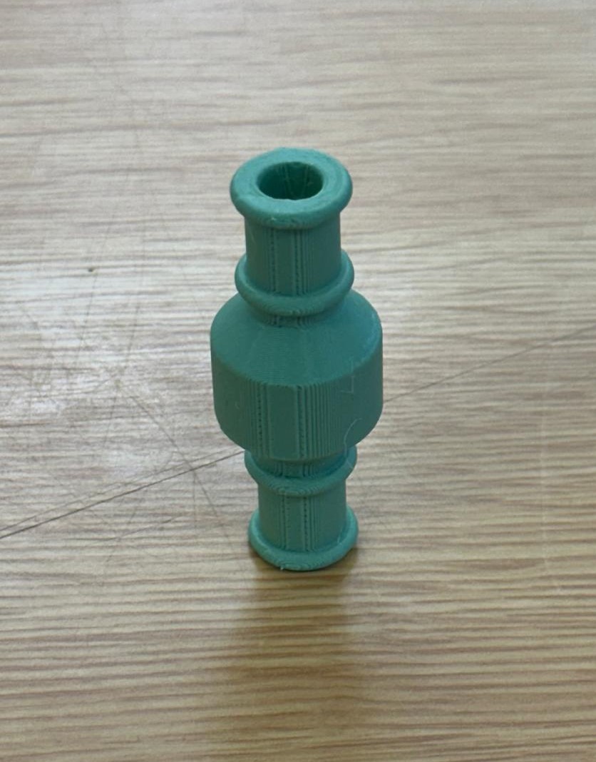
This validation stage proved essential before moving on to the mold design, as it confirmed that the simplified geometry of the object adequately fulfilled its functional purpose, thus avoiding investing time and resources in developing a mold for a part that had not yet been tested.
Mold design
For this version, a two-way demolding design was chosen instead of the one-way demolding used in the first version. This meant that, in addition to the opening between the two main pieces along the horizontal plane, the secondary pieces corresponding to the hole guides had to be removed vertically, perpendicular to the main parting line. This configuration increased the overall complexity of the structure and required the incorporation of additional elements to keep all the pieces properly joined during the injection molding process. Likewise, the design also considered reducing unnecessary resin usage, avoiding solid sections that did not serve a direct structural function.
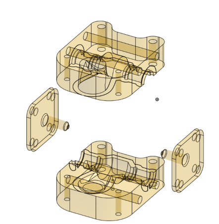
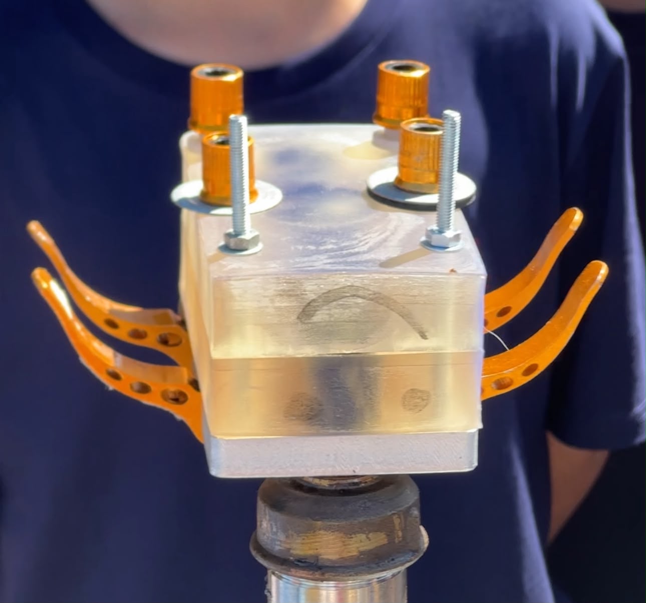
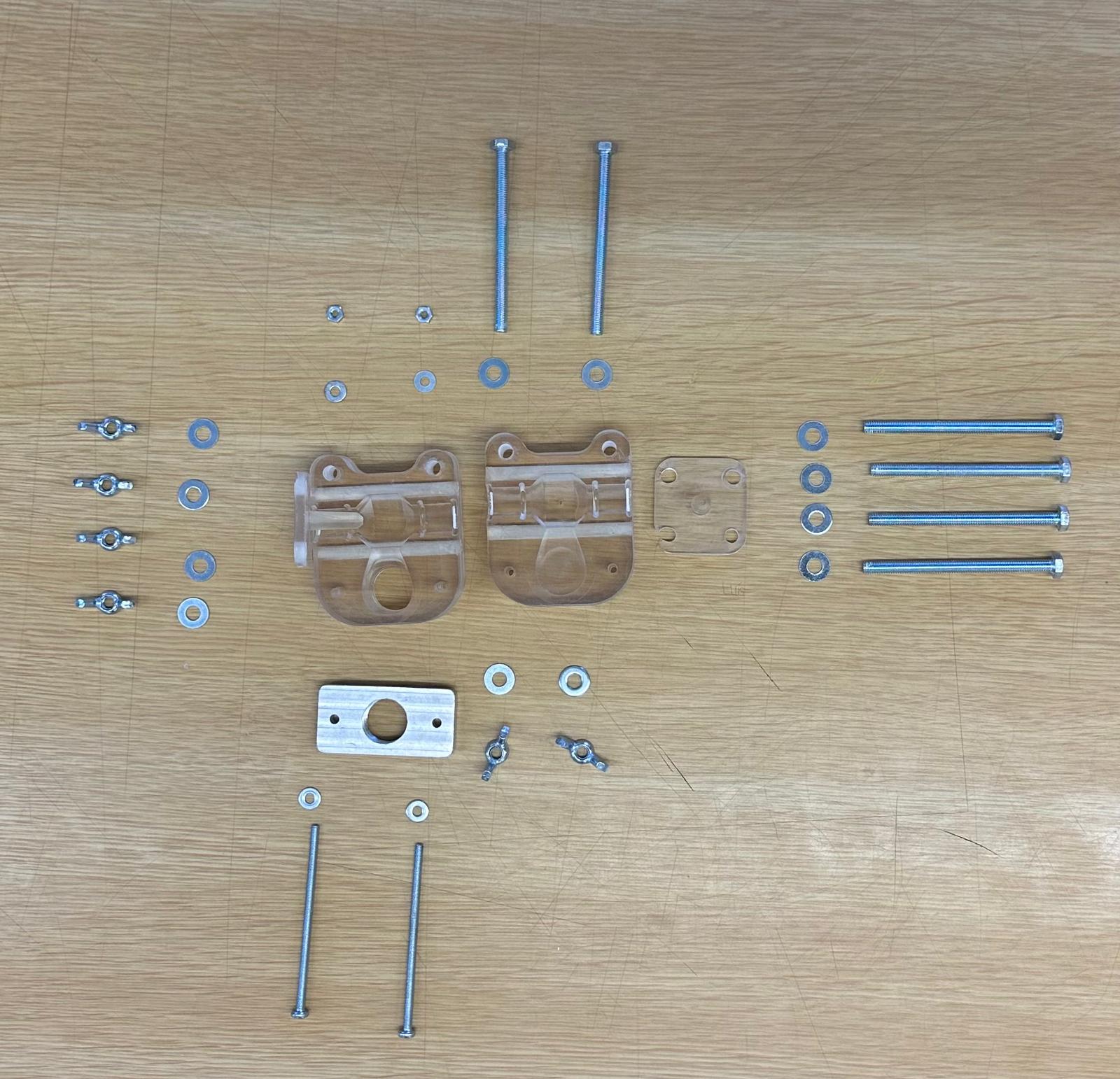
As a result, the assembly comprises an upper mold half and a lower mold half, which together define the cavity geometry of the hose coupling. Two interchangeable cavity inserts are incorporated to form the internal features of the part and facilitate demolding. An injection bracket is attached to the base of the mold to provide a secure connection between the injection cartridge and the mold entrance, for proper delivery of the molten plastic. The assembly is secured using M6 and M4 stainless-steel screws, washers, and nuts, which provide uniform clamping pressure, maintain alignment between the mold halves, and prevent leakage during injection. Additionally, dedicated venting passages are included to allow trapped air to escape during cavity filling, improving the quality of the molded component by reducing the formation of voids and incomplete filling.
Resin printing
In order to investigate the cause of the dimensional differences observed between the digital model and the part obtained from the mold of the first version, additional measurement verifications were performed before proceeding with the printing process for this second version. To this end, a small test cube was printed, including a semicircle similar to those present in the connector model, with the aim of isolating the geometric variable and evaluating whether the previously observed deformation was due to the part's design or the printing process itself. Measurements of the result confirmed the existence of a deformation, which was attributed to the 3D printing settings used, indicating that this factor needed to be adjusted to prevent the same problem from recurring in subsequent mold iterations.
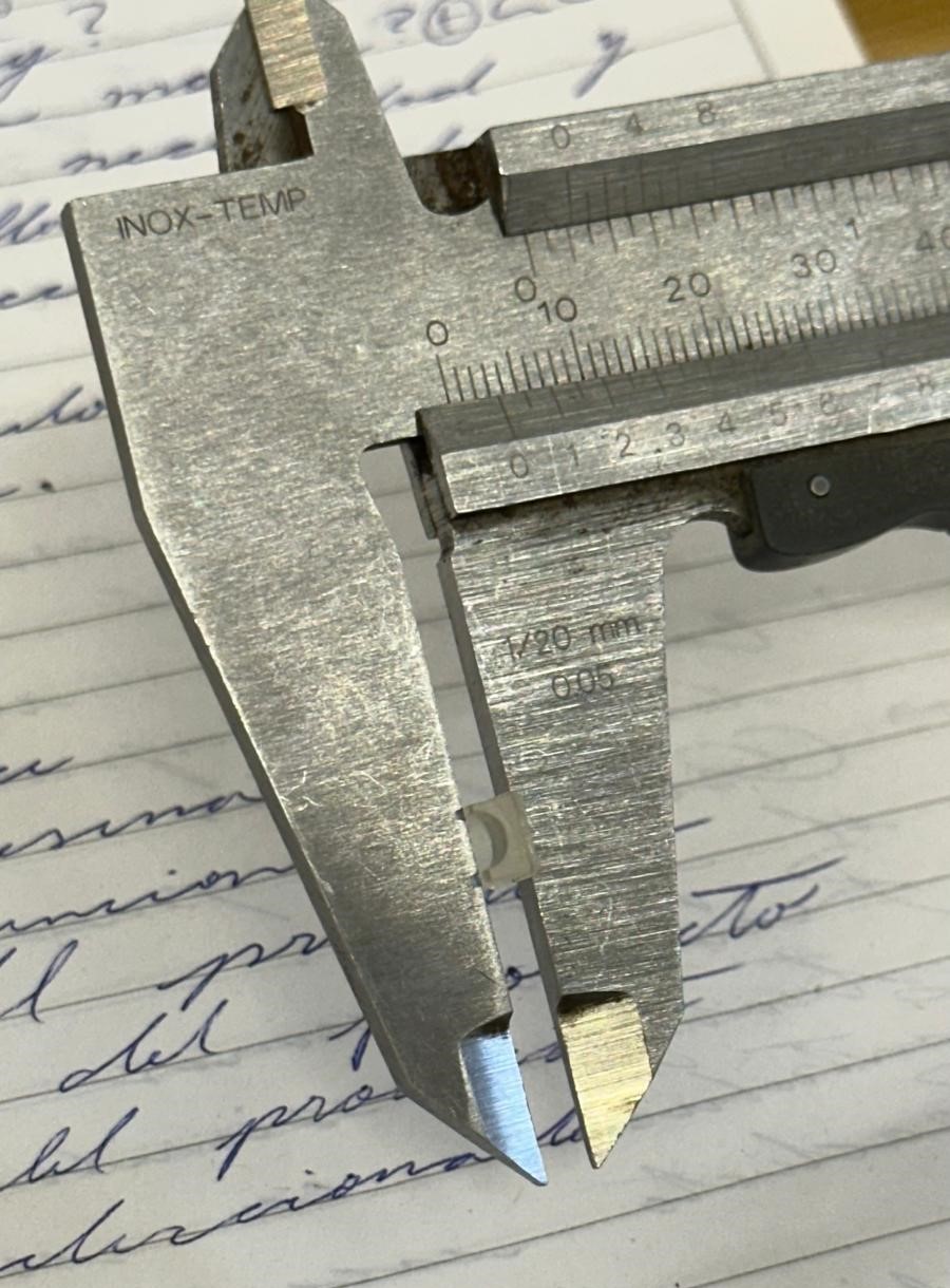
Despite the prior checks performed with the test cube, it was also decided to directly compare the injection-molded part with the original 3D model to more accurately quantify the magnitude of the deformation. To do this, one of the circumferences of the injected part was measured, yielding a value of 24.3 mm, compared to the 28 mm established in the digital model. This difference definitively confirmed the existence of a material shrinkage problem. Therefore, it was decided to adjust the model's shrinkage factor to 115.23%, calculated by dividing the original diameter of the 3D model (28 mm) by the diameter measured on the actual part (24.3 mm) and multiplying the result by 100, thus compensating for the material shrinkage during the injection molding process.
Once the model's shrinkage factor was adjusted, the resin printing of the mold was carried out, following the same process described above: orientation of the parts without supports, printing on the Uniformation GKtwo printer, washing with water due to the type of water-washable resin used, and subsequent UV curing in the UniCubic machine.
Solar Injection
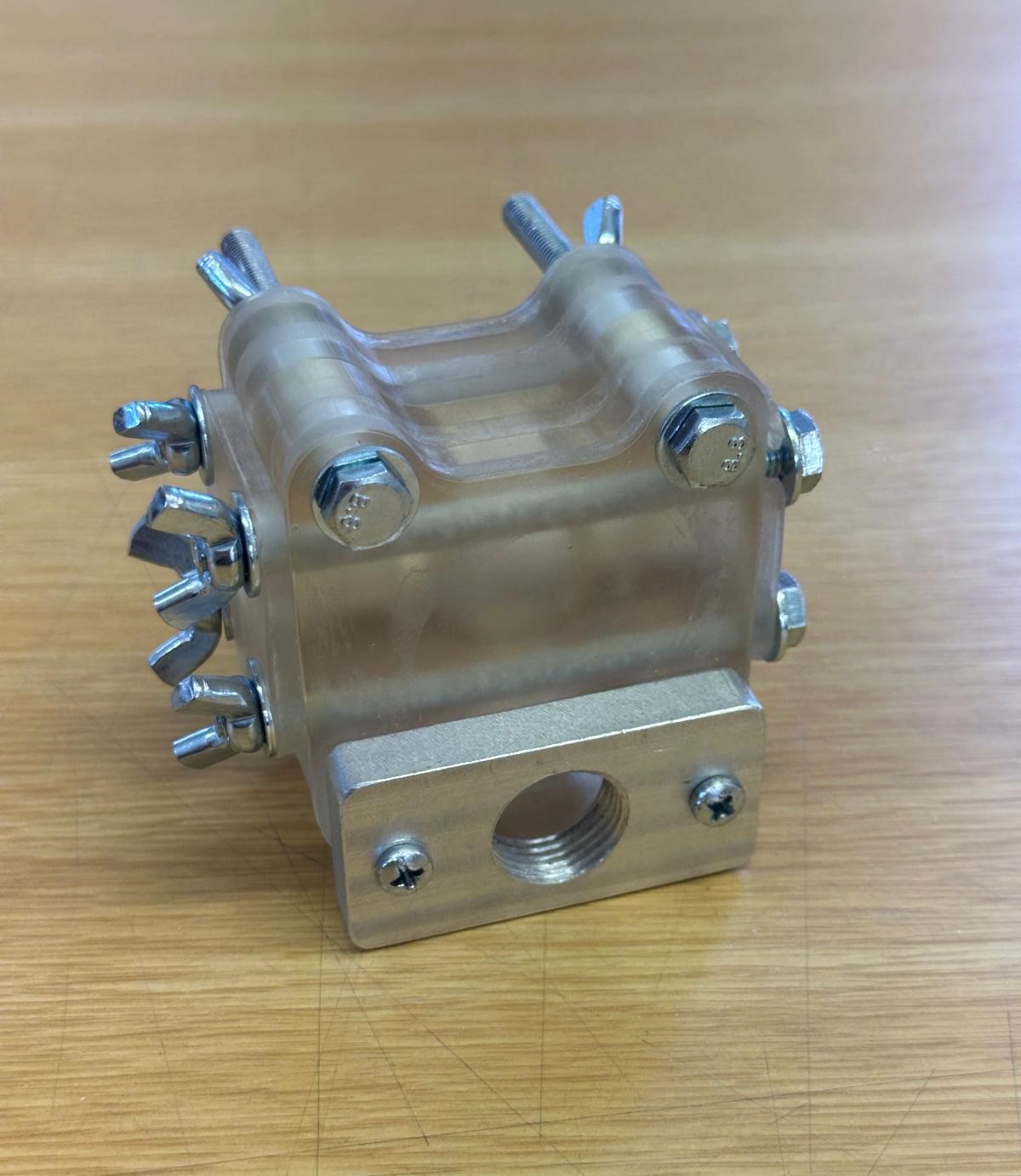
While everything was being prepared to melt the plastic, the mold was simultaneously being assembled and readied for injection, a process that proved somewhat more complex than in the previous version. This added complexity stemmed from the two-direction demolding design, which required additional screws to keep all pieces securely closed and aligned throughout the injection process, unlike the simpler single-direction closure used in the first mold.
This is the appearance of the mold following preparation:
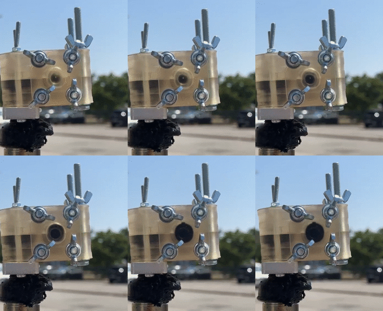
For this round of injection, the material used was BIO4-PLA520, a compound consisting of polylactic acid (PLA) reinforced with 20% (w/w) hemp cellulose (Bio4plas, 2021). Unlike the recycled HDPE used in the previous test, this bio-based composite combines a biodegradable polymer matrix with a natural fiber reinforcement, offering an alternative material profile with potentially different thermal and mechanical behavior during the solar injection process. The use of this compound aligns with the broader sustainability focus of Sun Factory project, further exploring how bio-based and reinforced materials perform within a solar-powered manufacturing setup.
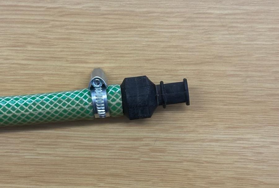
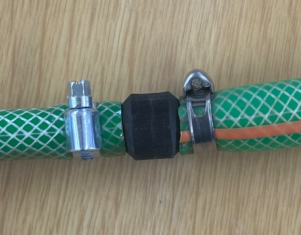
Upon completion of the preparation process, the hose connector was completed and it successfully attaches to the hose, secured in place with a metal hose clamp, and exhibits a solid, well-defined structure with clearer edges compared to the rougher finish observed in the initial prototype. The matte, dark texture of the piece reflects the composition of the BIO4-PLA520 material.
As observed in the image below, the second version of the connector successfully joins two hoses of different diameters, held in place with metal hose clamps on each end. Despite the diameter mismatch between the two hose sections, the connector performs its intended function, with a secure connection between them. This result highlights a practical advantage of the design: its ability to accommodate slight variations in hose diameter while still maintaining a functional, secure coupling.
Although this version of the connector proved to be functional, there remains space for improvement in future iterations of the project. For example, since the model is easily scalable, future versions could be developed at different sizes to accommodate a wider range of hose diameters without requiring a complete redesign. Additionally, the secondary mold pieces should be made thicker, as they proved to be fragile during the first round of testing and drilling, and increasing their thickness would improve their durability and resistance throughout the demolding and post-processing stages.
Applications
The process behind this hose connector, low-cost solar injection combined with 3D-printed molds, holds particular value for communities with limited access to industrial manufacturing infrastructure or conventional plastic recycling facilities. Rural or off-grid communities, where electricity access may be unreliable or costly, stand to benefit directly from a manufacturing method that relies solely on solar energy, enabling local production of functional plastic parts without dependence on external supply chains.
Educational institutions and community workshops also represent an important audience for replicating this process, as a means of producing useful objects and as a hands-on tool for teaching concepts of sustainability, recycling, and renewable energy, as demonstrated during the workshop conducted with children as part of this project. Similarly, small-scale manufacturers, makerspaces, and NGOs focused on circular economy initiatives could adopt this approach to develop their own customized tools and fittings tailored to local needs, using recycled plastic sourced directly from their communities.
Beyond those capable of producing the piece, a broader audience stands to benefit simply from having access to a functional, low-cost hose connector. Smallholder farmers and gardeners relying on basic irrigation systems represent a key group, particularly in regions where commercially manufactured fittings may be expensive, difficult to source, or unavailable in the specific sizes needed for their existing hose infrastructure.
Additionaly, field researchers working in remote or hard-to-reach locations, such as biologists, geologists, or climate scientists conducting fieldwork far from urban infrastructure, could also benefit from this type of solution. In these settings, access to replacement parts or hardware stores is often nonexistent, and equipment failures, such as a broken hose fitting in a water sampling or irrigation setup, can significantly disrupt fieldwork. Having the ability to produce a functional connector on-site, using recycled plastic and solar energy offers a practical, self-sufficient solution for maintaining equipment in isolated research environments.
Conclusions
The Sun Factory project is presented through the Antena Foundation, and this research was carried out as part of an internship at the FabLab Lisbon. As such, this work stands as a project aligned with Antena Foundation's core focus on developing sustainable technological solutions to meet the basic needs of marginalized populations, grounded in principles of sustainable development and social justice. Framed within this collaborative environment, the development of the hose connector served as a technical exercise in product design and solar plastic injection, and also as a practical demonstration of how open, accessible fabrication tools can support decentralized, community-driven solutions to plastic waste and energy access, reinforcing the broader mission that connects the Antena Foundation and the Sun Factory project.
Serving a purpose that extends beyond its function as a hose fitting, the connector developed throughout this project demonstrates that everyday, functional objects can be successfully produced through a decentralized process, combining recycled plastic, 3D-printed molds, and solar-powered injection. Each stage of the workflow, from product selection and 3D modeling to mold design, manufacturing, and testing, was validated as a replicable process capable of transforming plastic waste into a genuinely useful product without reliance on conventional industrial infrastructure, making this exercise a practical proof of concept for the broader Sun Factory methodology. Solar-powered plastic injection was thus confirmed as technically viable, and adaptable enough to accommodate design iterations and material variations, reinforcing its potential as an accessible manufacturing alternative for communities seeking sustainable, low-cost solutions to both plastic waste and limited access to conventional fabrication tools.
From a technical point of view, through the adjustments made between the first and second versions, the flattening issue observed in the initially injected piece was successfully corrected, resulting in a more dimensionally accurate connector and confirming the value of the iterative, trial-and-error approach followed throughout the project. Besides its immediate function, this outcome is useful in demonstrating that community-scale manufacturing can achieve results comparable to conventional production methods, empowering communities to take ownership of their own fabrication processes rather than depending on external, industrially manufactured parts. As an open-source project, all designs, molds, and processes developed throughout this work remain freely accessible to anyone wishing to replicate or adapt them, opening the door for similar everyday objects, beyond the hose connector itself, to be fabricated using the same solar-powered, recycled-plastic methodology.
Ultimately, the improvements achieved between both versions, particularly the correction of the flattening issue present in the first injected piece, illustrate the value of an iterative design process in reaching a functional, dimensionally accurate result. This outcome is useful as a validated solution for hose repair and connection and as an evidence that community-scale, solar-powered manufacturing can reliably produce everyday objects with consistent quality. By keeping all designs, molds, and processes open source, this project ensures that its results remain freely accessible to anyone wishing to replicate them, empowering communities to fabricate not only this specific connector, but a wider range of similar objects suited to their daily needs, using recycled plastic and solar energy as the foundation for a genuinely accessible, self-sufficient manufacturing approach.

Bibliography
Anjos, C. (2026). Individual assignment. Fab academy. Retrieved from: https://fabacademy.org/2026/labs/benfica/students/carlos-anjos/Week-17/individual.html
Bio4plas (2021). BIO4-PLA520. Retrieved from: https://bio4plas.com/es/produtos/bio4-pla520/
Collister & Glover (2024). Hose Connectors Explained – Which One Do You Need?. Retrieved from: https://www.colglo.co.uk/blog/hose-connectors-explained/
Fablab Benfica (2026). Knowledge base link. Retrieved from: https://gitlab.com/fablabBenfica/sun-factory/sun-factory-residency-2026/-/tree/knowledgebase
Nalgene (2025). ¿Cuánto tarda en degradarse una botella de plástico? Retrieved from: https://www.nalgeneiberia.com/blog/reciclaje/ciclo-de-vida-de-las-botellas-de-plastico-recicladas/
National Geographic (2024). ¿Qué es el plástico y por qué tarda tanto en degradarse?. Retrieved from: https://www.nationalgeographic.com.es/medio-ambiente/preguntas-y-respuestas-sobre-plasticos_22266
United Nations (n.d.) Objetivos y metas de desarrollo sostenible. Retrieved from: https://www.un.org/sustainabledevelopment/es/sustainable-development-goals/
Pinto da Costa, J., Rocha-Santos, T., Duarte, A. C. (2020). The environmental impacts of plastics and micro-plastics use, waste and pollution: EU and national measures. Retrieved from: https://www.europarl.europa.eu/RegData/etudes/STUD/2020/658279/IPOL_STU(2020)658279_EN.pdf
🌍 Join the Solar Movement
This work is part of the Sun Factory open-source initiative. We invite makers, engineers, designers, and enthusiasts worldwide to:
-
Replicate these technologies in your community
-
Improve the designs and share your modifications
-
Translate documentation into your language
-
Connect with the global Sun Factory network
🔗 Learn more: sunfactory.world
📜 License & Acknowledgments
This article is released under CC BY-SA 4.0 (Creative Commons Attribution-ShareAlike).
You are free to: Share and adapt this material.
Under the terms: Credit Sun Factory & author, share under same license.
🙏 Thanks to: FabLab Lisbon, Antenna Foundation, and the Sun Factory community.
Please log in or sign up to comment.